Building the ai03 Soyuz
by Zubair Abid
So I got a couple of B-Stock ai03 Soyuz PCBs from StacksKB for soldering practice, and about three months later I’m in the mood to make it a functional macropad.
This is not the proper build guide, I’m not using stabilisers for example. For that I’d recommend the build guide on ai03’s github. There are some oversights in that text guide with respect to microcontroller and diode soldering that I’ll be covering in this blog.
Config: Since this is my first use of QMK, this will also log my initial QMK
setup. The initial plan was to also showcase the configuration in this post,
but I am lazy and time is short. It will come in the next post, maybe.
This build does not use a tactile reset switch (I use tweezers directly) but it is recommended if you can get your hands on some.
Components used in the build
- 1
xai03 Soyuz PCB (came with break-off top and bottom FR4 plates) - 20
xIN4148 through-hole diodes - 4
x14mm M2 spacers (I recommend getting 16-20mm if you socket the microcontroller) - 8
x5mm M2 screws 40xMillmax 0305 sockets- Machined IC Socket (round holes)
- 1
xElite C v4 - 20
xBoba U4T
Technically, I also used
- A pair of tweezers for shorting pins (reset button, basically)
- Foam and tape, for some of the hacks.
Build
Soldering diodes
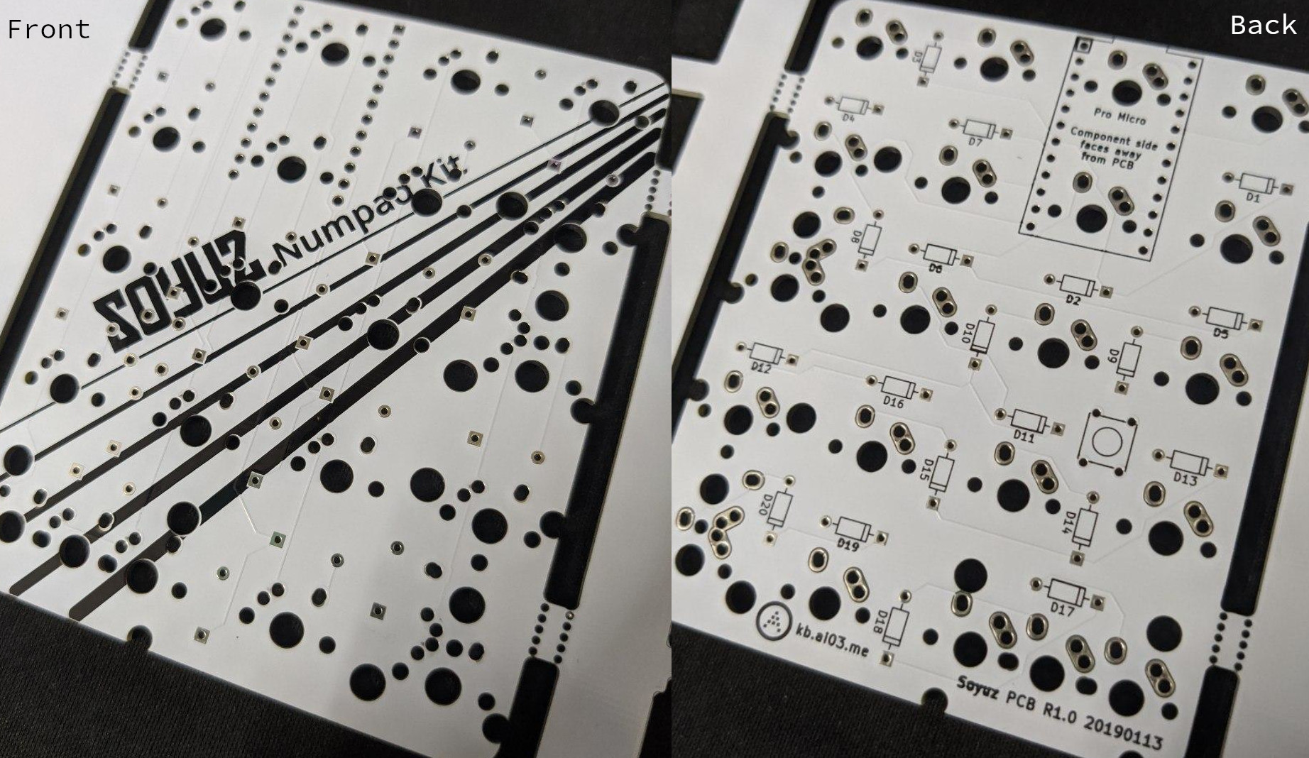
Diodes can theoretically be soldered on either side of the PCB, but it’s much more convenient if you solder them on the back – opposite of where the switches will be put. If the PCB you got retains the silkscreen art, the backside is the side opposite it.
More importantly, the diodes should be installed such that the polarity is not reversed. The PCB silkscreen shows the orientation to use. If messed up in a consistent fashion, it would be possible to fix it in the firmware, but this is still just hearsay to me. You’ll have to look up how.
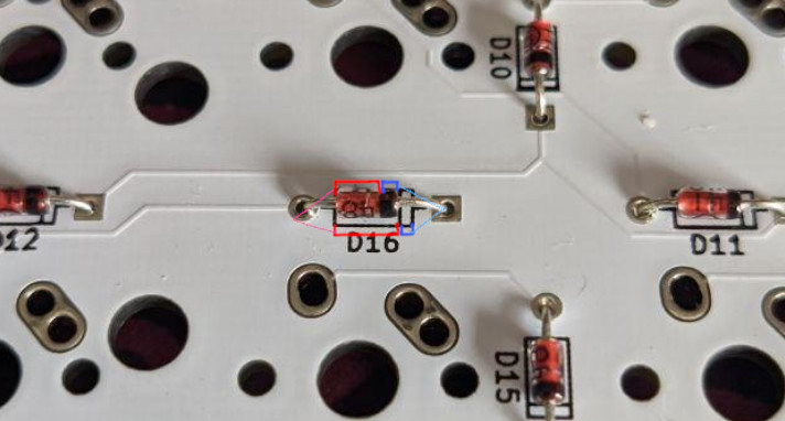
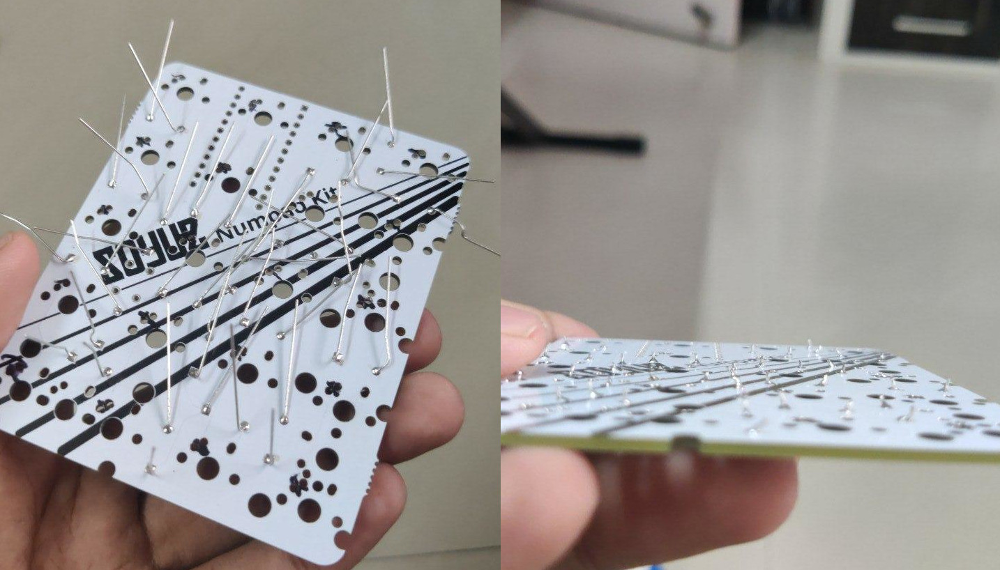
Installing them is easy: bend the legs to fit them, solder them in, and then clip off the diode legs. Keep the diode legs. They will be needed for socketing the microcontroller.
Socketing the microcontroller
Important: If you are not socketing your microcontroller, install the switches first. The microcontroller once installed, blocks two switch holes, so the switches cannot be soldered in after the fact. Unless you desolder the microcontroller – and good luck with that.
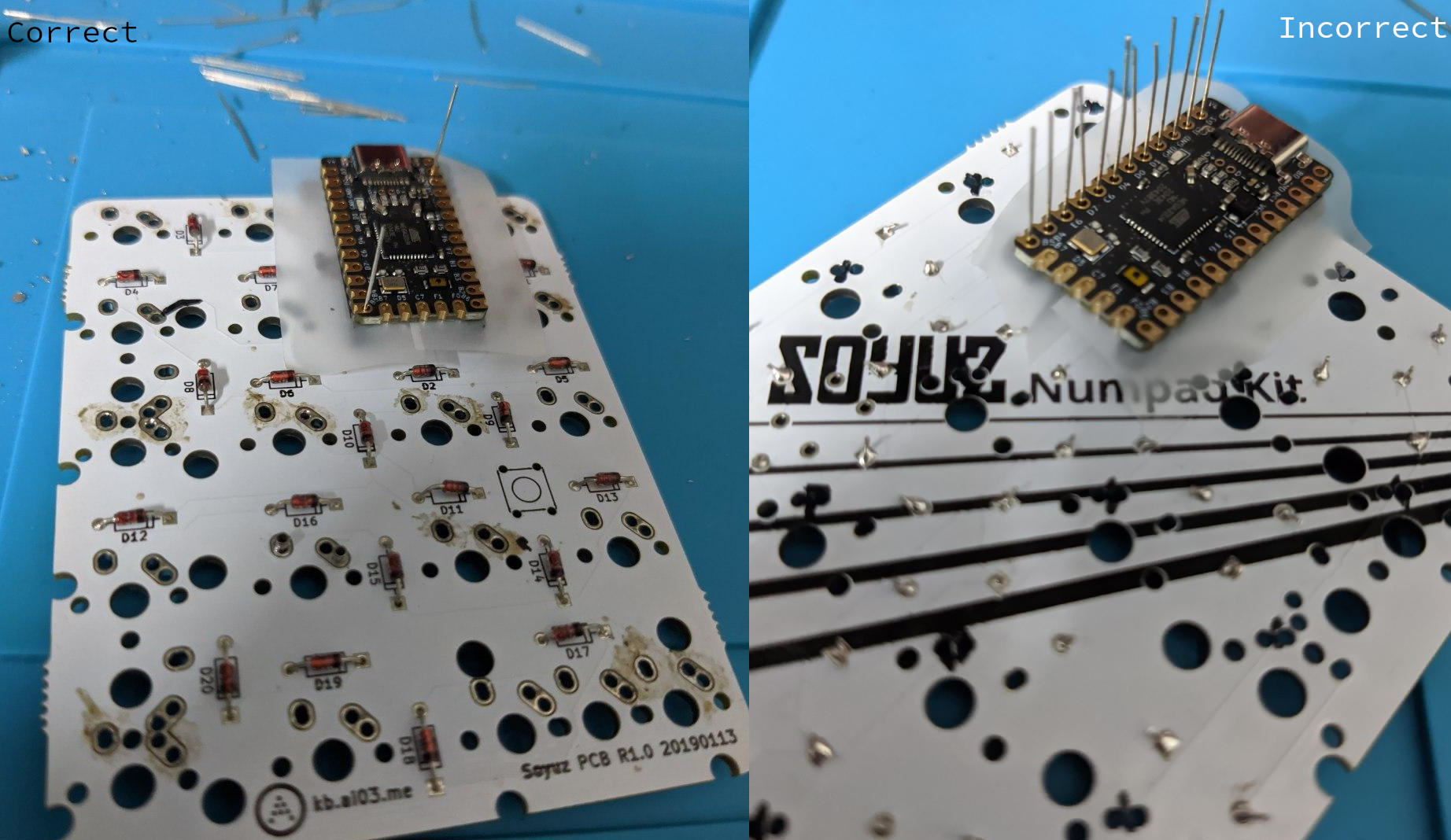
Even more important: Here, installing on the right side of the board is crucial. Ensure the microcontroller/socket is installed on the back of the PCB, where we just soldered on the diodes. If you mess this up, it would still be possible to run the numpad with 18 keys instead of 20 by installing the microcontroller backwards.
Also note that the correct way to install the microcontroller is with the side with the components facing away from the PCB. The silkscreen should specify this, but in case it didn’t, the more you know.
Instead of soldering the microcontroller onto the board, I socketed it using some 28-pin machined sockets I had to clip to size. This is a good resource for how to socket your microcontroller, but I’ll reproduce the basics on here. Socketing is generally a good idea even if you don’t plan on switching out the microcontroller. If you mess up soldering while building it, sockets are far cheaper and more disposable.
-
Put your sockets into the board and solder one pin.
If it’s a single line of sockets, we want it to be aligned straight. For that, heat the soldered pin up, and adjust the socket so it is perfectly straight at a 90° angle.
I got the idea from Nicell’s Lily58 Pro build stream, timestamped link to the video.
Confirm that the socket is on the right side of the board before soldering the rest of the pins in.
-
Tape over the socket holes to prevent the microcontroller from fusing with the socket. Using the diode legs from earlier, poke holes in the tape. It should look something like this:
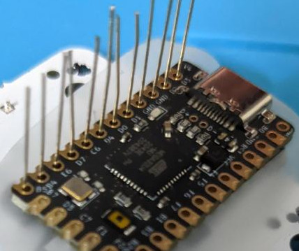
-
Put the microcontroller in through the diode legs. Solder at the base. Clip off the extra legs.
Testing the PCB
Now is a good time to test the PCB. Plug it in, flash the controller with the basic .hex file to start1, and test all the switch slots by shorting them with tweezers.
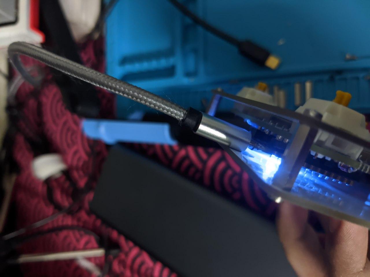
Mill-max vs soldering: Testing clearance
I initially planned to mill-max the Soyuz. The initial concern was that the PCB would fall off as it was not soldered in with the switches, but that proved to not be a concern in the short test I did.
The concern was that after socketing the microcontroller, there is almost no clearance for the USB cable as the port is inset (this will depend on the sockets you get). In my case, there is barely enough clearance on soldering switches in, but when mill-maxed (as the switch sits a bit higher, and thus the PCB a bit lower), there is none.
Hacks/Mods
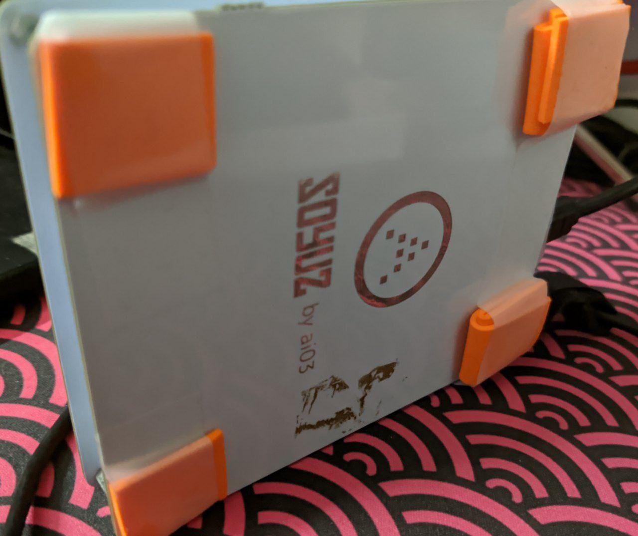
I currently do not have rubber feet, and the screws are scratching my deskmat.
-
Link to be added. For now, the StacksKB discord soyuz channel should have one ↩
<-- Back